
Complete engineering guide to machining POM (polyoxymethylene) — the most machinable engineering plastic for precision moving parts
In One Sentence
POM (acetal) is widely considered the most machinable engineering plastic — it cuts cleanly, holds tight tolerances, and offers low friction and excellent dimensional stability — but its sensitivity to heat and internal stress means process control is still essential for high-precision parts.
📱 **Mobile users: swipe left/right to view full table.**
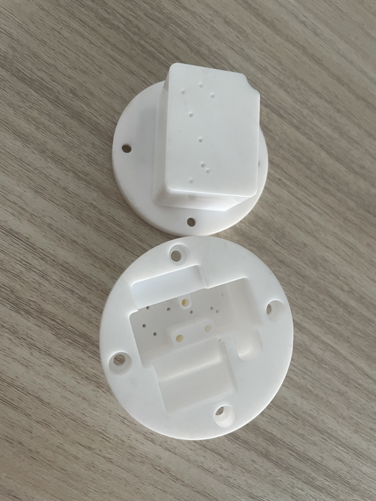
CNC Machined POM Part from Our Shop
1. What Is POM?
POM (polyoxymethylene), also known as acetal or by the brand name Delrin, is a high-crystallinity engineering thermoplastic. With a crystallinity of 75–85%, it behaves like a hard, brittle solid at the cutting edge — chips fracture cleanly rather than tearing, which is why it machines so well.
It offers high strength (tensile strength ~60–70 MPa), good stiffness, low friction coefficient (0.20–0.35), and exceptionally low moisture absorption (<0.25% in 24 hours). These properties make it ideal for precision mechanical parts that need to move, slide, or maintain tight fits over time.
There are two main grades:
POM-H (homopolymer, e.g., Delrin): Higher stiffness and tensile strength — roughly 5–10% more than POM-C. Preferred for gears and structural components.
POM-C (copolymer): Slightly lower mechanical strength but better chemical resistance, thermal conductivity during machining, and reduced centerline porosity. Preferred for parts with tight tolerances.
2. Key Material Properties
Understanding POM’s properties helps explain why it machines so well — and what its limitations are.
| Property | Value | Why It Matters |
|---|---|---|
| Tensile Strength | ~60–70 MPa (H: ~69–72 MPa / C: ~60–64 MPa) | Strong for a plastic — handles structural loads in moving parts |
| Yield Strength | ~61 MPa | Resists permanent deformation under load |
| Elongation at Break | ~25% | Bends before it breaks — good toughness |
| Hardness | Rockwell M80–M90 | Hard enough to hold detail, soft enough to machine fast |
| Thermal Conductivity | ~0.31 W/m·K | Higher than most plastics — heat dissipates reasonably well |
| Max Service Temp | 85–90°C continuous / 140°C short-term (peak only, not sustained) | Not for high-heat applications — PEEK handles much higher temperatures |
| Density | 1.39–1.42 g/cm³ | Lightweight — about half the weight of aluminum |
| Friction Coefficient (vs steel) | 0.20–0.35 | Naturally lubricious — self-lubricating for sliding parts |
| Moisture Absorption (24 hrs) | <0.25% | Excellent dimensional stability — no conditioning needed before machining |
| Machinability | Excellent | Considered the most machinable engineering plastic |
3. POM vs PEEK: When to Choose Which
Since we’ve already covered PEEK in a previous guide, here is a direct comparison to help you decide which material fits your application.
| Property | POM (Acetal) | PEEK | Practical Implication |
|---|---|---|---|
| Cost | ~$ (low) | ~$$$$ (high) | POM is significantly more economical |
| Machinability | Excellent | Good | POM is easier to machine, suitable for fast production |
| Max Continuous Service Temp | ~85–90°C | ~250°C | PEEK handles much higher temperatures |
| Tensile Strength | ~60–70 MPa | ~100 MPa | PEEK is stronger |
| Friction Coefficient | Very low (self-lubricating) | Low | Both are good for moving parts |
| Chemical Resistance | Good | Excellent | PEEK resists a wider range of chemicals |
| Moisture Absorption | <0.25% | ~0.1% | Both are dimensionally stable |
| Best For | Cost-sensitive moving parts, gears, bushings, low-friction slides | High-heat, high-strength, aerospace, medical, semiconductor |
When to choose POM: Gears, bushings, rollers, sliding components, low-friction parts, cost-sensitive projects, general mechanical assemblies.
When to choose PEEK: High-temperature applications, chemically aggressive environments, aerospace or medical components, applications requiring maximum strength and long-term reliability.
4. Machining POM: Parameters & Best Practices
4.1 Recommended Cutting Parameters
POM machines more like soft aluminum than like other plastics. It produces short, predictable chips at high speeds and holds tight tolerances without humidity conditioning.
For milling POM with carbide end mills:
| Parameter | Roughing | Finishing |
|---|---|---|
| Cutting Speed | 150–250 m/min | 250–350 m/min |
| Feed per Tooth | 0.10–0.25 mm/tooth | 0.05–0.10 mm/tooth |
| Axial Depth of Cut | 2.0–4.0 mm | 0.3–0.8 mm |
| Spindle Speed (typical) | 10,000–18,000 RPM | 12,000–24,000 RPM |
| Feed Rate (typical) | 1,800–4,000 mm/min | 1,500–3,000 mm/min |
For turning POM:
| Parameter | Roughing | Finishing |
|---|---|---|
| Cutting Speed | 200–400 m/min | 300–500 m/min |
| Feed Rate | 0.15–0.30 mm/rev | 0.05–0.12 mm/rev |
| Depth of Cut | 1.5–3.0 mm | 0.3–0.8 mm |
These parameters typically produce a surface finish of Ra 0.4–1.6 μm as-machined. Achievable tolerances range from ±0.02 mm to ±0.10 mm, depending on part geometry and fixturing.
4.2 Tool Selection
Use sharp uncoated carbide tools or PCD (polycrystalline diamond) tools
Positive rake geometry (6°–10°) reduces cutting force and heat generation
2-flute end mills are preferred for slotting and profiling
Avoid dull tools — they generate friction and heat, causing smearing and surface defects
Tools with larger corner radii improve surface finish
4.3 Coolant Strategy
POM has a relatively high melting point (175°C for POM-H), but local overheating can still cause edge melting, smearing, or surface degradation.
Recommended:
Air blast or air cooling — removes chips and cools the cutting zone without any risk of affecting material stability
Mist or micro‑lubrication — can be used for light cuts
Coolant considerations:
Short-term water-based flood cooling can be used if needed — many shops run it successfully on POM
However, avoid prolonged immersion in flood coolant. Long-term wet exposure may introduce dimensional shift and surface contamination. If flood coolant is used, parts must be fully dried after machining
For most applications, air blast remains the preferred primary cooling method
5. Distortion Control in POM Machining
For a detailed guide on thin‑wall distortion causes and prevention strategies, see our CNC Machining Distortion Control guide.
POM is sensitive to two main deformation risks:
5.1 Heat Sensitivity
Localized heat buildup during machining can cause edge melting, smearing, surface whitening, or even tool adhesion. Since heat is the enemy, the core principle for POM machining is: medium speed with high feed — the goal is a “quick separation” cut rather than a “rubbing” cut.
A practical rule: avoid running at the very high end of the speed range with very low feed per tooth — that combination creates rubbing friction rather than clean cutting, which is what generates heat. For roughing, target the lower half of the speed range with higher feed; for finishing, keep speed moderate and feed light enough for surface quality, but not so light that the tool rubs.
Heat control best practices:
Use sharp tools — dull tools generate friction heat
Avoid high speed with low feed — this creates rubbing, not cutting
Use air blast for cooling and chip removal
Avoid prolonged local cutting — keep toolpaths moving
5.2 Internal Stress Release
POM contains internal stresses from extrusion or molding. When you machine away material, these stresses rebalance and the part can warp or spring back — especially on thick sections or complex geometries.
Stress control best practices:
Step 1 – Roughing: Remove the bulk of material quickly but with controlled depths of cut to avoid local overheating.
Step 2 – Semi‑finishing: Reduce cutting depth significantly and use stable toolpaths. Layer‑by‑layer stock removal allows the material to gradually release internal stress, reducing warpage and spring‑back.
Step 3 – Stress relaxation pause: If practical, allow the part to sit (on a flat surface) for several hours between roughing and finishing to let residual stress redistribute. (Note: This is most practical for high‑precision one‑off parts. For mass‑production workflows, optimized stock allowance and controlled cutting sequences are often used instead of long dwell pauses.)
Step 4 – Finishing: Use light cuts with sharp tools. For high‑precision parts, complete the job in a single setup to minimize clamping errors and ensure coaxiality and perpendicularity.
5.3 Fixturing for POM
POM is stiffer than many plastics, but thin sections can still deflect under clamping pressure.
Do this:
Soft jaws — machined to match your part shape
Vacuum fixtures — even pressure across the whole surface
Low clamping pressure — just enough to hold, not enough to deform
Single‑setup machining — for high‑precision parts, avoid re‑fixturing
Avoid:
Over‑tightening — POM can deform under excessive clamp pressure
Localized clamping — point loads can cause distortion
6. Common Applications for POM CNC Parts
POM is specified when low friction, wear resistance, dimensional stability, and cost‑effective machining are the priorities. Typical applications include:
Gears & sprockets: Precision gears, timing pulleys, worm gears
Bearings & bushings: Plain bearings, flanged bushings, thrust washers
Sliding components: Guide rails, slides, linear motion components
Automotive: Fuel system components, instrument clusters, seat belt mechanisms
Medical devices: Surgical instrument handles, drug delivery components, diagnostic equipment parts (only use ISO‑compliant medical‑grade POM grades; standard‑stock POM is not biocompatible)
Food processing: Conveyor components, FDA‑compliant parts (POM‑C FDA grades available)
Industrial automation: Pick‑and‑place fingers, grippers, locating pins, fixture components
Consumer products: Zipper parts, power tool components, appliance mechanisms
7. Common Machining Problems & Solutions
| Problem | Cause | Solution |
|---|---|---|
| Edge melting or smearing | Excessive heat, dull tool | Reduce cutting speed, increase feed (quick separation), use sharper tool, add air blast |
| Surface whitening or hazing | Rubbing rather than cutting, dull tool | Increase feed, replace with sharp tool |
| Part warps after unclamping | Internal stress release | Use rough‑semi‑finish‑finish sequence with stress relaxation pause |
| Tool adhesion (built‑up edge) | Dull tool, wrong geometry | Use sharp positive‑rake tool, increase coolant/air, reduce feed |
| Poor surface finish | Dull tool, incorrect feed | Replace tool, optimize feed per tooth |
| Chatter or vibration | Low rigidity setup, too much tool overhang | Shorten tool overhang, use larger tool diameter, reduce radial depth of cut |
| Dimensional drift | Heat buildup, or material stress release | Control temperature, allow stress relaxation between stages, use air cooling |
| Chip packing in deep pockets | Poor chip evacuation | Use compressed air for chip clearing |
Need help with your POM CNC project?
Whether you need gears, bushings, sliding components, or custom precision parts — we machine POM (acetal) to tight tolerances every day. Contact us and send your 2D drawings & STEP 3D files to our team, and we’ll review the geometry and recommend the right material grade and machining strategy.
References
POM (acetal) material properties and grade comparisons
CNC machining parameters for engineering plastics
Distortion control for precision plastic machining
Editorial Note
This document is educational content built on industry‑standard practices for POM CNC machining. All process data is for reference only. Always validate cutting parameters, material grade, and distortion mitigation strategy against your actual stock condition, machine tool capability, and tooling setup before formal production.